What is meant by an injection moulding simulation?
INJECTION MOULDING SIMULATION
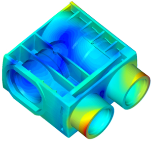
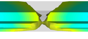
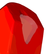
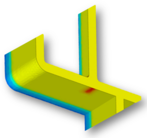
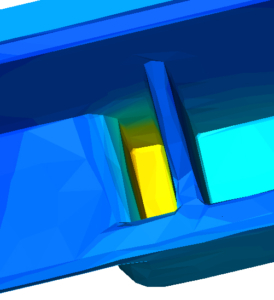
An injection moulding simulation shows the process of filling and cooling (thermoplastics) or cross-linking (silicone/rubber) with the influence of the mould (e.g. temperature control and injection situation) even before the mould is designed.
Qualified simulation and the expert interpretation of the results allow possible moulded part and tooling defects to be detected at an early stage. This is the basis for component optimisation.
Fundamentals of the injection moulding simulation
The combination of an injection moulding simulation of the actual state, a view on the simulation of a temperature control of the future mould, the component optimisation and the subsequent simulation of the optimised state with regard to component and temperature control does not only enable very precise simulation and optimisation results.
The fact that the most important influencing variables can be included in the development of the product means that the first samples can already be produced with good parts more and more frequently.Since the geometric part optimizations generally also enable a significantly shorter cycle, the previous additional effort pays off several times over. The time to the finished product is significantly reduced, quality is improved and the unit price is also lower due to a better process window with a shorter cycle time.
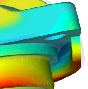
After the part optimisation has been carried out, the possible cold and holding pressure stresses, and thus the distortion, are reduced. Now, if necessary, a negative correction of the part can also be made. We create these in compliance with the tangential contour transitions. This manipulated geometry is then worked into the tool so that warpage is reduced to a minimum.
We simulate:
- filling
- Shrinkage and warpage
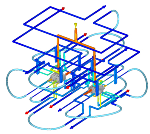
- mould temperature control
- feed situation
- holding pressure profile
- thermoplastics
- process parameters
- different media and materials
- inserts / overmouldings
We analyse:
- warpage
- cycle time
- clamping forces
- part defects
- injection pressure on cores
- identifiable potential for optimisastion
- planning and calculation
Our Offer:
- simulation of the results from parts optimisation
- calculated negative correction
- allowance determination for for parts reinforced with glass fibres
- creation of tool concepts as a basis for the simulation
Your benefits:
- high process reliability
- higher component quality
- avoiding revisions
- optimal preparation of tool design
- when implementing results into IsoForm® tool design good parts frequently at first sample run
Welche Daten müssen bei einer Simulation eingegeben werden?
Je genauer die Einfluss-/Eingabefaktoren und IST-Daten, desto genauer die Simulationsergebnisse
Materialdaten
Thermoplaste + Additive
Elastomere
Stähle
Metalle
Nichtmetalle (Einleger / Hart-Weichkomponenten / Werkzeug / Einsätze
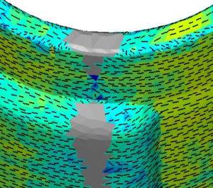
Faserorientierung
Besonders bei Bindenähten
Verzug
Schwindungsunterschiede
Montage , Passungen und Funktionsmaße
Geometrie
- Datenqualität
- kunststoffgerechte
- Form / Auslegung
- Funktion
- Wandstärken
- Festigkeit
- Vernetzung
- Negativkorrektur
Bindenähte
Belastung und Optik
Fließverhalten
Wo müssen Fließhilfen und Wandstärken reduziert werden
Fließverhalten
Wo müssen Fließhilfen und Wandstärken reduziert werden
Angusssituation
- Heißkanal / Düsenart
- Kaltkanal
- Verteilersystem
- Totkanal
- Angussgeometrie
- Anschnitts-geometrie
Druckbedarf
In der Kavität, sollte 800bar nicht übersteigen
Schließkraft, Maschinenauswahl, Anspritzung, Fließhilfe
Nachdruckwirkung
Wo müssen Fließhilfen und Wandstärken reduziert werden
Nachdruckwirkung
Wo müssen Fließhilfen und Wandstärken reduziert werden
Lufteinschlüsse
Erstarren der Fließfront
Auswerferposition, Entlüftung, Dieseleffekt, Standfestigkeit
Entlüftungen
Geometrisch verhindern oder über Normalien entschärfen
Werkzeug-temperierung
- Zyklusabhängig
- konturnah
- Turbulente Strömung
- Querschnitte
- Normalien
- Medium
- Kreisläufe
Lunker/Vakuole
- Potential in Dickstellen
- Einfall – / Glanzflächen
- Lunker und Vakuolenbldung
Wandstärke
- Unterschiede
- Gewichteinsparung
- Zykluszeit
- Nachdruckwirkung
Prozess-parameter
- Füllzeit
- Nachdruckzeit
- Nachdruckstufen
- Kühlzeit
- Nebenzeit
- Zykluszeit
- Zulauftemperaturen
- Einlegetemperaturen
HOT-Spots
Wo fehlt eine konturnahe Temperierung
Wandtemperatur bestimmt die Zykluszeit, Entformungsprobleme
Temperierwirkung
Wodurch entsteht keine turbulente Strömung
